

Calculation of seismic loads for analysis of structure is required when earthquake resistant structure is to be designed. Structural Engineers use different design codes/guidelines for calculation of earthquake loads. Widely accepted codes for calculation of seismic loads are, Uniform Building Code 1997 (UBC-97), International building code (IBC), ASCE-7-10, Building code of Pakistan (seismic provisions), Indian standard (IS-1893). Here in this article we shall cover the method of calculating seismic forces defined in UBC-97.
Earthquake loads are determined on the basis of seismic zone, site characteristics, occupancy category, structural configuration and structural system. Earthquake resistant structure must withstand forces and displacements induce by ground motion during event of earthquake. In section 1626, UBC defines:
The purpose of the earthquake provisions herein is primarily to safeguard against major structural failures and loss of life, not to limit damage or maintain function.
It means that earthquake resistant structures are designed to prevent life loss and major structural failures, minor damage within acceptable limit may occur during earthquake.
Terminologies
Z = Seismic Zone Factor, See Table 16-I
I = Seismic Importance Factor, See Table 16-K
R = Ductility Coefficient, See Table 16-N
Ca = Seismic Coefficient, See Table 16-Q
Cv = Seismic Coefficient, See Table 16-R
Na = Near Source Factor, See Table 16-S
Nv = Near Source Factor, See Table 16-T
Design Data
Before starting calculations for seismic forces, you need to make following data available.
Occupancy Category, I
Section 1629.2 Occupancy categories defines importance factor I or Ip for each category. The importance factor is useful when base shear is calculated. For Importance factor, please see table 16-K provided in UBC-97.
Soil Profile Type
Soil profile type is determined based on different properties of soil and generally provided in soil investigation report for the site. UBC-97 defines Soil Profile Types SA, SB, SC, SD and SEin Table 16-J, Soil Profile Type SF is also defined but as soils requiring site-specific evaluation. please see table 16-J provided in UBC-97.
Seismic Zone
Seismic zone is most important element in determining seismic forces. according to UBC-97 guidelines, Each structure shall be assigned a seismic zone factor Z, in accordance with Table 16-I. Now the question is how to determine seismic zone for some particular area? UBC-97 defines seismic zones for USA in figure 16-2. For other areas on globe, seismic zone maps are available over internet (must be obtained from authentic source).
Seismic Response Coefficients , Ca & Cv
Seismic coefficients Ca and Cv are used to calculate base shear. these coefficients and dependent on soil profile type and seismic zone factor. Values for Ca and Cv are provided in table 16-Q and table 16-R, respectively.
Near Source Factor for Zone 4, Na & Nv
For sites located in Zone 4, near source factors Na and Nv are assigned according to seismic source type and distance from the seismic source. Seismic source type is defined in Table 16-U. Values for Na and Nv are provided in tables 16-S and 16-T, respectively. These factors are then used to calculate seismic response coefficients for zone-4.
Calculating Seismic Loads
Base Shear, V
Uniform building code (UBC-97), defines base shear as total lateral force at bottom of structure due to ground motion during an earthquake.
When following, section 1630.2 Static Force Procedure, total design base shear (V) in a given direction shall be calculated using following formula.

The total design base shear calculated from above equation should be lesser than the following

But, it shall be greater than the following.

In addition, for Seismic Zone 4, the total base shear shall also greater than the following.

T, in equation 30-4, is time period for building/structure in seconds. T can be calculated using following formula.

where,
Ct = 0.035 (0.0853) for steel moment-resisting frames.
Ct = 0.030 (0.0731) for reinforced concrete moment-resisting frames and eccentrically braced frames.
Ct = 0.020 (0.0488) for all other buildings.
hn = Total height of structure above the base.
* values in ( ) to be followed when using metric system of units.
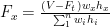
Vertical Distribution of Shear (Story Shear), Vx
The design story shear, Vx, in any story is the sum of the forces Ft and Fx above that story. The base shear calculated from above set of equations is distributed over the height of the building according to the following Equation.
Where

Ft should be < 0.25V for T > 0.7 seconds

The shear force at each story is then calculated using following equation.

Where,
n = number of stories above the base of the building
Ft = the portion of the base shear, concentrated at the top of the structure to account for higher mode effects
Fi, Fn, Fx = Lateral forces applied at levels i,n,or x, respectively.
hi, hn, hx = Height above the base to levels i,n,or x, respectively
Vx = design shear in story x
Horizontal Distribution of Shear
Story shear, Vx shall be distributed to the various elements of the vertical lateral-force-resisting system in proportion to their stiffness. Distribution of story shear shall be in form of ‘horizontal torsional moments’ and ‘overturning moments’.
Story Drift, ΔS
The story drift ΔS, corresponding to the design seismic forces calculated above shall be determined using dynamic analysis techniques. Expression for Maximum Inelastic Response Displacement, ΔM is used for calculation the story drift.
ΔM = 0.7 R ΔS UBC Eq. (30-17)
Vertical Component
The requirement of calculation vertical component for seismic forces is applied in Seismic Zones 3 and 4 only. Horizontal cantilever components shall be designed for following net upward force.

In addition to all other applicable load combinations, horizontal prestressed components shall be designed using not more than 50 percent of the dead load for the gravity load, alone or in combination with the lateral force effects.
Hello
Thank you. Very good and simple explanation for calculating Seismic loads.
This will be very much useful for NON-CIVIL/STRUCTURAL engineers.
Can you please clarify Seismic acceleration??
Many times Customers provide only Seismic acceleration and soil type. They do not provide Seismic zone in their specification.
Does this information sufficient ? Do we need to get any additional information ?